In electrical power systems, current and voltage have to be measured accurately for the safety of the system operation and its protection purposes. High-current or high-voltage measurements may not be easy or even dangerous at all. Instrument transformers such as Current Transformer (CT) and Potential Transformer (PT) come into play in such cases.
While both are meant to step down high electrical values to a level that could easily be used by measuring and protecting devices, there is a clear difference between these two types of transformers in terms of functions, wiring, and application.
What Is a Current Transformer (CT)?
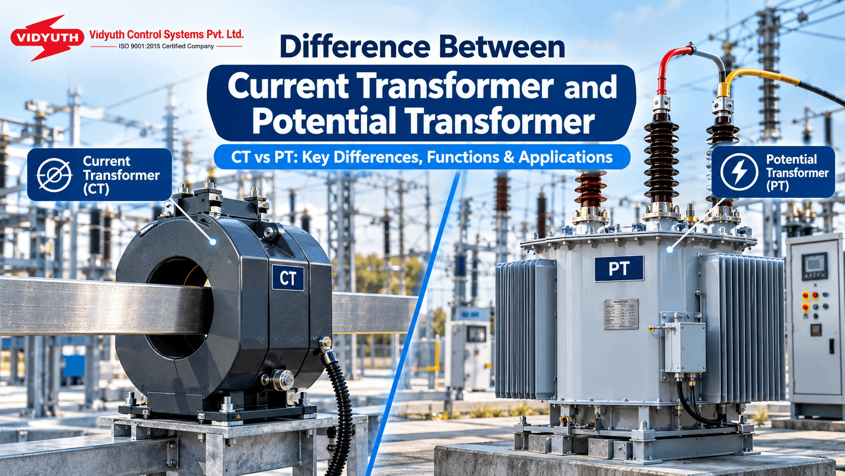
Current transformer is an instrument transformer which is utilized to measure alternating current especially when it has large magnitude. This device steps down a high primary current to a low level which can be measured by using an ammeter or by protective relay.
CT can step down a high primary current to a secondary current having standard values like 1 Ampere or 5 Ampere. The current from the secondary winding of a CT can be used for the purpose of measuring or by protective relays. The primary winding of CT is connected in series with the transmission line.
CTs come in various types, such as the wounded and the closed-core type. The core of the CT is usually made of silicon steel laminations.
What is a Potential Transformer (PT)?
A Potential Transformer, which is also referred to as a Voltage Transformer, is used for measuring high voltage. It does not decrease current but reduces high voltage to standard low levels.
The PT can step down high voltage to a secondary voltage of 100V or less. The PT isolates high-voltage circuits from humans or measurement instruments that are connected to it.
Unlike the CT where the primary windings are in series connection with the circuit, in the case of PT, the primary winding is in parallel with the circuit and hence carries the line voltage across its terminals.
Difference Between CT and PT
The key differences can be understood through their construction and operating characteristics:
| Parameter | Current Transformer (CT) | Potential Transformer (PT) |
|---|---|---|
| Main function | Measures and reduces high current | Measures and reduces high voltage |
| Connection | Connected in series | Connected in parallel |
| Primary winding | Fewer turns and carries the current being measured | More turns and carries the voltage being measured |
| Secondary winding | More turns; commonly produces 1A or 5A | Fewer turns; commonly produces around 100V or lower |
| Transformation ratio | High | Low |
| Core | Silicon steel laminations | Steel core designed to operate at low flux density |
| Measurement example | A 5A ammeter can measure a high current such as 200A | A 120V voltmeter can measure a high voltage such as 11kV |
| Secondary circuit | Should not be open-circuited during service | Can be open-circuited without damage |
| Applications | Current and power measurement, grid monitoring and protection | Voltage measurement and protection |
This difference indicates that despite CTs and PTs having similar functions of reducing high electrical quantities for easy measuring, they have different specifications.
Also read – Core type and shell type transformer difference
CT PT Transformer: How Do They Serve Power Systems?
The ct pt transformer system can be applied in cases where there is need to measure both current and voltage. The CT will supply a reduced current to the meters and protective relays while the PT will supply a reduced voltage.
Their secondary side behavior is yet another vital difference between the two. The secondary side of a CT transformer must not be kept open during use while the secondary side of a PT transformer may be kept open. The secondary current of a CT may be 1A or 5A while the secondary voltage of a PT may be 100V or less.
It is thus clear that both transformers play an important role in monitoring electrical circuits as well as protection devices.
Selection Criteria Between CT and PT
This decision is based mainly on the measurement criteria to be met. For instance, when there is a need to measure a high current and to generate a low current output signal for a measuring instrument or a relay, then CT is suitable. When the aim is to measure high voltage through low voltage with a proportional value, PT is needed.
In order to select one of the two instruments appropriately, an engineer must understand the differences between their connections, winding design, transformation ratio, core design, and secondary use.
Conclusion
The main difference between the current transformer and the potential transformer is that each transformer measures a different electrical parameter. The CT step down high current into low secondary current, while the PT steps down high voltage into low secondary voltage. The CT is connected in series, and the PT in parallel. There are also differences in their windings, ratio, secondary, and applications.
Choosing the appropriate instrument transformer is crucial for ensuring accurate measurements and protection within the electrical system. In order to learn more about other types of transformers, you can refer to the core and shell type transformer difference.
Looking for a Reliable CT & PT Transformer Manufacturer?
If you are in need of an effective CT PT Transformer Manufacturer in India, Vidyuth Control Systems can provide you with information about transformer solutions that suit your needs. For more details, contact us today regarding your CT PT transformers requirements.